
What Is a Current-Drive Amplifier?
How it works, where it helps and where it does not, and what it measurably does to loudspeaker distortion — with the numbers from three drivers.
A current-drive amplifier (also called a transconductance, current-source or current-output amplifier) controls the current through the loudspeaker’s voice coil instead of the voltage across its terminals. Its output impedance is high — many times the driver’s impedance — where a conventional amplifier’s is close to zero. Because the force that moves the cone is proportional to current (F = B·l·i), holding the current to the signal removes the distortion that a voltage amplifier lets in when the voice coil’s impedance changes with frequency, cone position and temperature.
- The third harmonic falls by about 24 dB on the Visaton BG20 with a single 2 kHz tone; the fifth and seventh harmonics fall close to the measurement noise floor.
- The second harmonic can remain similar, as in the BG20 1 kHz spectra, even when higher-order harmonics fall. A single THD figure does not show which harmonics changed.
- Third-order intermodulation falls 4–17×: two-tone IMD (DIN) on a SEAS FA22RCZ from 0.54 % to 0.12 %, its MD3 from 0.53 % to 0.031 %.
- The benefit depends on frequency and driver. The sine-sweep graphs show different harmonic changes across the range. Near resonance, reduced electrical damping also affects the result.
- Current drive works best on a driver connected directly to its own amplifier channel — not through a passive crossover.
- The Baffless amplifier is mixed-mode: voltage drive at low frequencies, current drive above, selected by a jumper.
How a current-drive amplifier works
Nearly every amplifier ever built is a voltage source: its output impedance is a fraction of an ohm, and it holds the voltage across the speaker terminals to the signal no matter what the driver does. The current that actually flows — and therefore the force on the cone — is whatever the loudspeaker’s impedance lets through. That impedance is not a constant. The voice-coil inductance changes with cone position and with the current itself (the iron in the magnetic gap saturates and modulates), and the coil’s resistance rises as it heats. Every one of those variations turns into a variation of current, and so into distortion and compression, before the amplifier can do anything about it.
A current-drive amplifier does the opposite. Its output impedance is high compared with the loudspeaker — ten times the driver’s impedance or more — so what follows the signal is the current through the voice coil. If the current is held to the signal, the impedance can vary all it likes: the force on the cone is B·l·i, and i is fixed. This can reduce distortion caused by changes in voice-coil impedance. Mechanical non-linearity of the suspension and of B·l over excursion remains, so different harmonics need not change by the same amount.
Such amplifiers are almost non-existent in audio. First Watt’s F1 and F2 are the best-known commercial examples, and they have a devoted following. It is not a universal upgrade: with a box speaker designed for voltage drive and using a passive crossover, current drive can do more harm than good. The outcome depends on the driver and crossover design: the crossover response can change, and electrical damping at resonance can be reduced. Driving a naked driver in an active open-baffle system — one amplifier channel per driver, no passive filters — it is close to ideal.
Voltage drive vs current drive
The difference is what the amplifier holds to the signal. A voltage amplifier fixes the voltage across the speaker terminals and lets the current follow the loudspeaker’s impedance. A current amplifier fixes the current through the voice coil and lets the voltage follow instead. Since the force on the cone follows the current, that choice decides which errors reach the sound.
| Voltage drive | Current drive | |
|---|---|---|
| What the amplifier controls | Voltage at the terminals | Current through the voice coil |
| Output impedance | Close to zero | High, ten times the driver’s impedance or more |
| Changing voice-coil impedance | Turns into current, so into distortion and compression | Largely ignored: the current is held to the signal |
| Third-order distortion (measured below) | Reference | About 20–24 dB lower third harmonic on the BG20; MD3 4–17× lower |
| Thermal compression | Level sags as the coil heats | None from coil resistance |
| Damping at resonance | Electrical damping from the amplifier | None: the bass resonance peaks unless DSP or mixed mode handles it |
| Passive crossovers | Designed for it | Response can change; best with one amplifier channel per driver |
So neither is better everywhere. Voltage drive is the safe choice for a passive box speaker. Current drive is cleaner above the resonance, on a driver with its own amplifier channel. The Baffless amplifier combines the two: mixed-mode drive, explained below.
Measured: what current drive changes in the distortion spectrum
All the results below are acoustic measurements taken with a microphone: the same driver, the same microphone position and the same level, with the amplifier switched between voltage mode and current mode. Nothing else changes. The animated graphs the numbers are read from are on the measurements page.
1. Sine sweep: harmonic levels across frequency
The sine-sweep graphs on the measurements page show how the third harmonic changes as the test frequency rises. The table below restores the approximate values read visually from those curves for the Visaton BG20 and Peerless HDS 830884.
Approximate visual readings of the third harmonic relative to the fundamental (dB) during sine sweeps. These are estimates from the source graphs, not calculated averages over each range or exact measurement data. Negative change means a lower third harmonic under current drive.
| Driver · level | Frequency range | Voltage drive | Current drive | Change |
|---|---|---|---|---|
| Visaton BG20 · 94 dB | 200–500 Hz | −61 dB | −60 dB | +1 dB |
| 500 Hz–1 kHz | −59 dB | −65 dB | −6 dB | |
| 1–2 kHz | −61 dB | −74 dB | −13 dB | |
| 2–4 kHz | −54 dB | −70 dB | −16 dB | |
| 4–8 kHz | −58 dB | −69 dB | −11 dB | |
| Visaton BG20 · 104 dB | 200–500 Hz | −57 dB | −57 dB | 0 dB |
| 500 Hz–1 kHz | −59 dB | −59 dB | 0 dB | |
| 1–2 kHz | −63 dB | −72 dB | −9 dB | |
| 2–4 kHz | −56 dB | −69 dB | −13 dB | |
| 4–8 kHz | −57 dB | −70 dB | −13 dB | |
| Peerless HDS 830884 · ~94 dB | 200–500 Hz | −64 dB | −74 dB | −10 dB |
| 500 Hz–1 kHz | −64 dB | −76 dB | −12 dB | |
| 1–2 kHz | −59 dB | −69 dB | −10 dB | |
| 2–4 kHz | −58 dB | −70 dB | −12 dB | |
| 4–8 kHz | −54 dB | −63 dB | −9 dB |
2. Single 2 kHz tone: the whole harmonic series, one driver
A single tone shows every harmonic at once. Visaton BG20, 2 kHz, fundamental at 81 dB on the graph scale, measurement noise floor about 88 dB below it.
Approximate harmonic levels read from the 2 kHz Visaton BG20 plots, relative to the fundamental.
| Harmonic | Frequency | Voltage drive | Current drive | Change |
|---|---|---|---|---|
| 2nd | 4 kHz | −74 dB | −78 dB | −4 dB |
| 3rd | 6 kHz | −53 dB (0.24 %) | −77 dB (0.014 %) | −24 dB |
| 5th | 10 kHz | −63 dB (0.073 %) | below noise (<−86 dB) | more than 23 dB lower |
| 7th | 14 kHz | −72 dB | below noise | more than 15 dB lower |
Under voltage drive the third harmonic is about 21 dB above the second. Under current drive the second and third are close in level; the fifth and seventh are near the noise floor. All levels here are approximate readings from the plots.
3. Two-tone intermodulation
Music is not a single tone. These are the measured results for the same two-tone signals under each drive mode. In the two-tone tests, the third-order products fall by a factor of about 4 to 17; the second-order MD2 figures rise slightly. The total distortion figures therefore change less than the third-order component.
Two-tone intermodulation, same signal and level under each drive mode.
| Driver | Tones | Metric | Voltage drive | Current drive | Ratio |
|---|---|---|---|---|---|
| SEAS FA22RCZ | 500 Hz + 1.6 kHz 116 dB peak | IMD (DIN) | 0.54 % | 0.12 % | 4.5× lower |
| MD3 (3rd-order) | 0.53 % | 0.031 % | 17× lower | ||
| MD2 (2nd-order) | 0.085 % | 0.099 % | slightly higher | ||
| TD+N | 0.84 % | 0.74 % | 1.1× lower | ||
| Peerless HDS 830884 | 500 Hz + 1.6 kHz | IMD (DIN) | 0.91 % | 0.33 % | 2.8× lower |
| MD3 (3rd-order) | 0.89 % | 0.20 % | 4.5× lower | ||
| MD2 (2nd-order) | 0.20 % | 0.25 % | slightly higher | ||
| TD+N | 0.53 % | 0.42 % | 1.3× lower | ||
| Peerless HDS 830884 | 200 + 333 Hz 94 dB | IMD (power) | 0.14 % | 0.071 % | 2× lower |
| DFD3 (3rd-order) | 0.094 % | 0.020 % | 4.7× lower | ||
| TD+N | 0.45 % | 0.38 % | 1.2× lower |
THD is the wrong number to look at
Both spectra below are the same Visaton BG20 fullrange driver, the same 1 kHz tone at the same acoustic level (81.9 vs 81.6 dB RMS), measured through a microphone rather than into a resistor. The only difference is how the amplifier drives it.
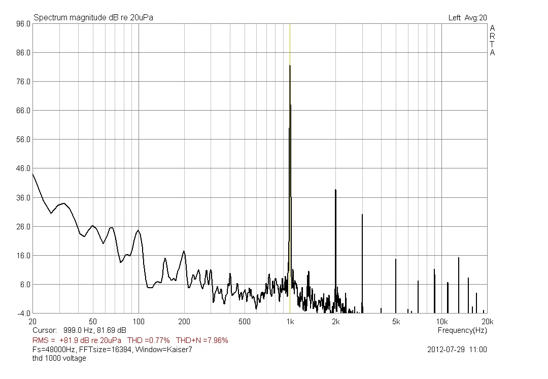
Pic. 1 — Voltage drive. THD 0.77 %. Note how the harmonic series keeps going: 2 kHz, 3 kHz, then a comb of higher-order products all the way out to 18 kHz.
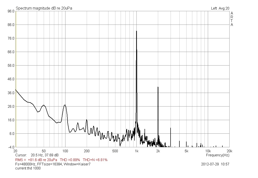
Pic. 2 — Current drive, same driver and similar level. THD 0.89 %, while the third-harmonic peak is much lower.
The displayed THD figure is higher under current drive: 0.89 % versus 0.77 %. The second-harmonic peak is at about the same level in both spectra, while the third harmonic drops by roughly 20 dB and many higher-order peaks shrink. These plots alone do not establish why the total THD figure rises.
THD combines all harmonics into one number, so it does not show which ones changed. In these spectra, several higher-order peaks shrink under current drive even though the total THD figure rises. With music made of many simultaneous tones, the added harmonic products may collectively mask quiet details, much like a raised noise floor. Reducing them may make more of the recording’s air and microdetail audible.
The same result on a different driver
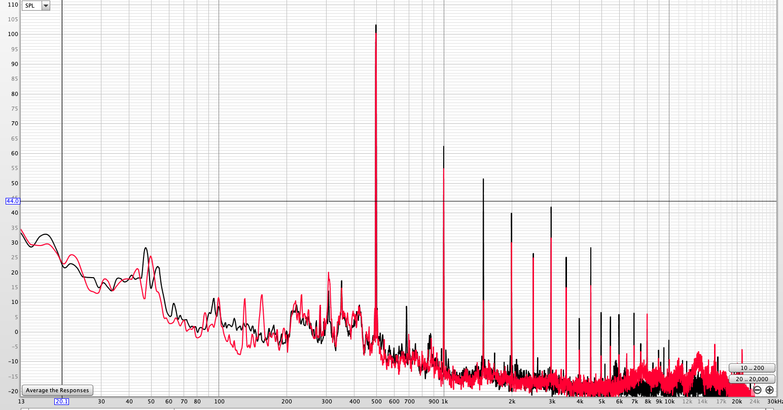
Pic. 3 — SEAS FA22RCZ fullrange, current drive (red) overlaid on voltage drive (black), tone near 490 Hz at about 103 dB. The second harmonic near 1 kHz is about 7 dB lower; the third, near 1.5 kHz, falls from about 51 dB to about 11 dB.
The pattern appears on a different driver too. The fundamental is nearly the same in both modes. The second harmonic is lower under current drive by about 7 dB here, and the third by about 40 dB. The effect varies by harmonic and test condition.
Benefits and limitations
What current drive gives you
- Lower third-harmonic and third-order intermodulation in the tests shown — about 20 to 24 dB lower for the BG20 single-tone examples, and third-order MD3 down about 4 to 17× in the two-tone tests.
- No thermal compression from voice-coil heating. A hot coil has a higher resistance; a voltage amplifier then delivers less current and the level sags. A current amplifier delivers the same current regardless.
- Immunity to cable and connector resistance — a few tenths of an ohm in series with the driver is invisible to a current source.
- More perceived air, microdetail and naturalness. With complex music, higher-order harmonics from many tones can build up and mask quiet details, much like a raised noise floor. Reducing those products may make the recording feel more natural.
What it costs, and where it does not belong
- No electrical damping at resonance. The driver’s effective Q rises to its mechanical Q, so the bass resonance peaks unless it is handled by DSP, by a driver with a suitably low Q, or by mixed-mode drive (below).
- The frequency response follows the driver’s impedance curve. The impedance rise at resonance and the inductive rise at high frequencies both appear in the acoustic output and must be equalised. In an active DSP system that is a one-time filter.
- Use caution with passive crossovers. A network designed for a voltage source can change its filter response under current drive, and electrical damping at resonance can be reduced. Whether the result helps depends on the speaker design.
Why valve amplifiers have been doing this by accident
A valve amplifier with modest feedback has a relatively high output impedance, so it operates part-way between voltage and current drive. Part of its reputation for sounding “pleasant” comes from exactly this mechanism: the driver connected to it produces fewer high-order harmonics. Current drive takes the same effect to its limit, without the rest of the valve amplifier’s compromises. With the high-order products gone, the result is more air, more lifelike, cleaner — a more relaxed listen rather than a more impressive one.
Mixed-mode drive: the Baffless implementation
Voltage drive supplies electrical damping at resonance; current drive can reduce particular distortion products at higher frequencies, as the measurements above illustrate. So the Baffless amplifier is mixed-mode by design: it behaves as a voltage source at low frequencies and as a current source higher up, with a jumper selecting pure voltage mode, mixed mode 1 or mixed mode 2. You get the damping where the driver needs it and the clean spectrum everywhere else. The board is a stereo, balanced-input analog amplifier; details are on the amplifier page.
Frequently asked questions
- Is a current-drive amplifier the same as a transconductance amplifier?
- Yes. A transconductance amplifier converts an input voltage into an output current, which is exactly what a current-drive amplifier does at its speaker terminals. “Current-source amplifier” and “current-output amplifier” mean the same thing.
- Does current drive reduce THD?
- It can reduce particular harmonics without lowering the displayed total THD. In the BG20 1 kHz spectra, the third-harmonic peak falls by roughly 20 dB while THD reads 0.77 % under voltage drive and 0.89 % under current drive. The second-harmonic peak is similar in both plots. Compare the spectra as well as the total figure.
- Can I use a current-drive amplifier with an ordinary loudspeaker?
- It depends on the speaker. A passive crossover designed for a voltage source can respond differently under current drive, and the driver may have less electrical damping at resonance. An active system with one amplifier channel per driver makes the result easier to control, ideally with DSP to equalise the response.
- Why does the bass change under current drive?
- A voltage amplifier damps the driver’s resonance through the voice coil; a current source does not, so the driver’s Q rises to its mechanical Q and the resonance peaks. This is why mixed-mode drive (voltage at low frequencies, current above) or DSP equalisation is used.
- Which current-drive amplifiers exist commercially?
- Very few. The First Watt F1 and F2 by Nelson Pass are the best-known examples. The Baffless analog current-drive amplifier board is a mixed-mode, jumper-selectable implementation.
- How were these measurements made?
- Acoustically, with a measurement microphone on the bare driver: swept-sine harmonic tracking, single-tone spectra and two- and three-tone intermodulation tests. For each pair the driver, microphone position and level are identical and only the amplifier’s drive mode is switched. The animated before/after graphs are on the measurements page.
- Is current drive better than voltage drive?
- Above the driver’s resonance it lowers the third-order distortion products, often by a large amount, as the measurements on this page show. At the resonance it removes the electrical damping, so the bass needs DSP or mixed-mode drive. Whether it helps a given speaker depends on its design; it suits active systems with one amplifier channel per driver best. See the comparison table.
- Where can I get a current-drive amplifier to try?
- The Baffless analog current-drive amplifier is a ready-made stereo board, assembled and tested, with balanced inputs and jumper-selectable voltage, mixed mode 1 and mixed mode 2. It costs 250 EUR plus shipping from Lithuania.
Read more about current drive
References
- P. G. L. Mills and M. O. J. Hawksford, Distortion Reduction in Moving-Coil Loudspeaker Systems Using Current-Drive Technology, Journal of the Audio Engineering Society, vol. 37 no. 3, March 1989. The founding paper; the physics has been settled for over thirty years.
- Esa Meriläinen, Current-Driving of Loudspeakers: Eliminating Major Distortion and Interference Effects by the Physically Correct Operation Method, 2010, and the companion site current-drive.info — the deepest resource on the subject.
- Baffless, Current drive vs voltage drive: animated measurements — additional animated comparison graphs.