
Flat Frequency & Phase
Frequency response sets the level of each frequency. Phase sets its timing relative to the others. Together they determine the waveform.
On loudspeaker graphs, “flat frequency response” usually means flat magnitude response: each frequency leaves the system at the intended level. That is important, but it describes only part of the signal. Phase response describes the timing of each frequency relative to the others. Magnitude and phase are the two parts of the same transfer function, and together they determine the waveform at the output.
Same frequencies, different waveform
Both examples below contain 200 Hz and 400 Hz components at the same amplitudes. In the first, their relative phase is 0°. In the second, only the 400 Hz component is shifted by 90°. The levels at 200 Hz and 400 Hz have not changed, but their time-domain sum clearly has.
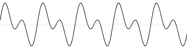
Pic. 1 — 200 Hz and 400 Hz at the same amplitudes and 0° relative phase.
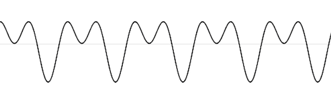
Pic. 2 — The same two frequency components after the 400 Hz component is shifted by 90°.
This comparison makes a precise signal-domain point: changing relative phase changes the reconstructed waveform. If a crossover adds frequency-dependent phase shift, the waveform leaving the loudspeaker is no longer identical to the source waveform, even when its magnitude response has been equalised flat. Whether a listener detects that difference is a separate question.
What happens through a crossover
In a multi-way loudspeaker, adjacent drivers overlap across each crossover region. Their acoustic outputs add according to both level and phase. The electrical filters, the drivers’ own responses and the distance between their acoustic centres all affect that sum. Poor phase alignment can cause reinforcement or cancellation around the crossover, and it changes the shape of the reproduced signal in the time domain.
Baffless uses FIR (Finite Impulse Response) filters in its active four-way crossover. FIR processing allows the magnitude and phase targets to be controlled together, so the drivers can be aligned from acoustic measurements of the complete loudspeaker rather than only from an electrical schematic.
Linear phase is not zero latency
A waveform-preserving system does not need every phase value to read 0°. Its phase may follow a straight slope with frequency, which represents the same fixed delay for every frequency — a constant group delay. A practical FIR crossover therefore adds processing latency, but that common delay does not alter the relative timing inside the signal. Frequency-dependent delay does.
Step and impulse response
Magnitude and phase plots describe the system in the frequency domain. Step and impulse responses show the combined result in the time domain, including the drivers, crossover filters and their acoustic summation. The following plots are the response examples published on the original Baffless page.
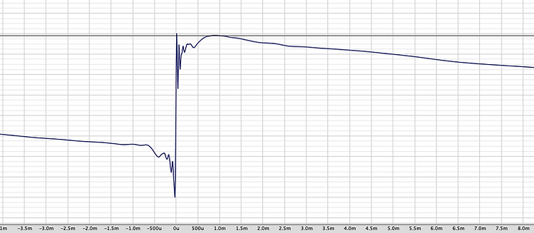
Pic. 3 — Step response of the system.
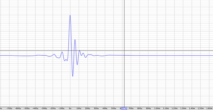
Pic. 4 — Impulse response of the system.
The Baffless design target is a flat acoustic magnitude response and controlled, linear phase through every crossover region. The purpose is straightforward: preserve the relationships contained in the recording, so the reproduced waveform stays as close as possible to the source apart from a fixed common delay and the unavoidable bandwidth limits of a real loudspeaker.